|
Approximate An Ideal
Low Pass Filter 理想低通滤波器的近似
Windows for FIR
Filter Design
FIR滤波器设计用的窗函数
Filter Features 滤波器指标
Steps of Windowed
FIR Design 窗函数FIR滤波器设计步骤
Examples
HomeWork: p379: 9.12, p380: 9.25
Approximate Ideal Low Pass
Filter
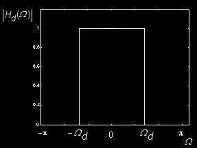
Ideal Low Pass
Filter Shape
Impulse Response of Ideal LPF
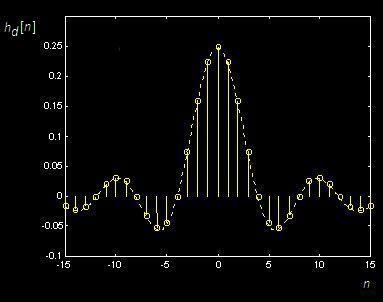
 Infinite Length, Non-Casual! Infinite Length, Non-Casual!
 Windowing! Windowing!
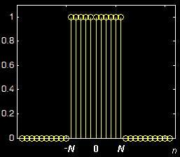
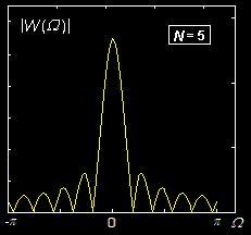
Rectangular Window
Its Frequency Response:
Multiply
hd [n] with Window w[n]:
h[n] = hd [n]
w[n]
H(Ω) =
Hd(Ω) * W(Ω)
Non-Ideal Low Pass
Filter Shape:
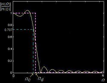
Cut-off
frequency: Ωc
20log|H(Ωc)|/|H(0)|
= 3 dB
Finite Length in
Time,
Smearing(拖尾) in Frequency.
|
Practicability
实用性
|

|
Quality
品质
|
Filter Features
Non-Ideal Low Pass
Filter Shape:
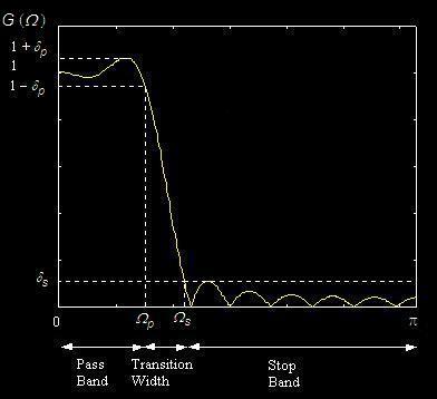
Pass
band edge frequency: Ωp
通带边缘频率
Stop
band edge frequency: Ωs
阻带边缘频率
Transition width: |Ωs - Ωp|
过度带宽
Pass
band ripple: dp
通带波纹
Stop
band ripple: ds
阻带波纹
Stop
band attenuation: -20log(ds)
阻带衰减
Windows for FIR
Filter Design
|
Hanning Window:
|
|n|
≤ N
|
|
Hamming
Window:
|
|n|
≤ N
|
|
Blackman Window:
|
|n|
≤ N
|
|
Kaiser Window:
|
Zero Order
Modified Bessel Function
零阶修正贝塞尔函数
|n|
≤ N
|
Steps
of Windowed FIR Design
Low Pass Filter
According to
the Given Filter Specification
{ fpass , fstop , fs,
ds }
----------------------------------------------------------------------
1. Set fd = (fpass+ fstop)/2
2. Compute
|
Ωd=
2π fd /fs ,
|

|
3. According to 20log(ds), From Table 9.3,
Choose w[n] and the Filter Length
(2N+1) .
4. Calculate impulse response
h[n] = hd[n]w[n].
5. Shift the h[n] to the
right by N samples.
------------------------------------------------------------------------
P345,
Example 9.7
Band Pass & High Pass
Filters
|
Band Pass Filter
{ fstop,
fpass, f0, fs, ds}
|
High Pass Filter
{ fstop, fpass
, fs, ds }
|
|
1. fd = f0
- (fpass+ fstop)/2
4. h[n]=hd[n]w[n]cos(nΩ0)
Ω0 = 2π f0
/ fs
|
1. fd = fs
- (fpass+ fstop)/2
4. h[n]=hd[n]w[n]cos(nπ)
|
P355, Figure
9.45
P359, Example 9.11
 Band Stop = Low
Pass + High Pass Band Stop = Low
Pass + High Pass
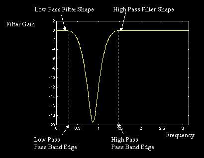
HBS(Ω) = HLP(Ω)
+ HHP(Ω)
hBS[n] = hLP[n]
+ hHP[n]
ΩpLP
< ΩpHP
Band
Pass = Low Pass
x High Pass
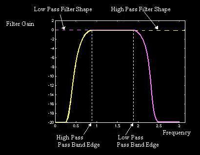
HBP(Ω) = HLP(Ω) HHP(Ω)
hBP[n] = hLP[n]
* hHP[n]
ΩpLP
> ΩpHP
.
Examples
Filtering
Speech
Original
Low Pass
Filtering High Pass
Filtering
Filtering Music
Original
Low Pass Filtering
|